Gryme & Dylapidaytid RR Roundhouse
at Gryme
This group of photos shows
the construction process of the HO/HOn3 (1/87 scale) Gryme & Dylapidaytid
RR Roundhouse located at the North end of the town of Gryme just below Gryme
Heights. Also included are some photos
of the Turntable and other accessories associated with the Roundhouse such as
the Power Plant for the Gryme Roundhouse.
Actual construction started in December of 2003 preceded by about 6
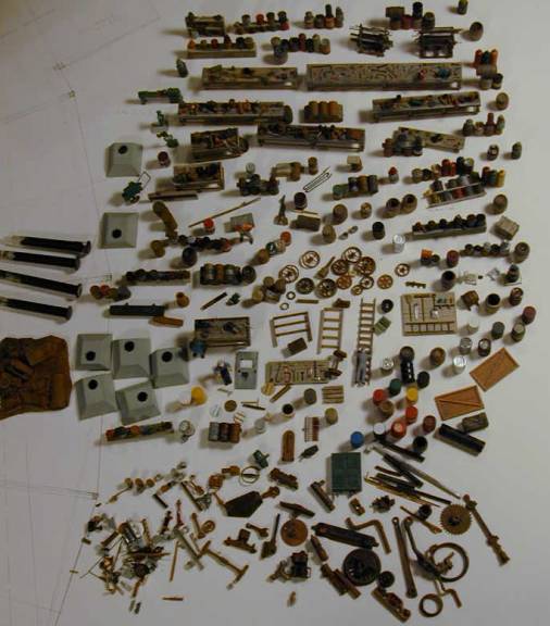
months of studying prototype photos, plans, sources of information, and
planning, including the detailed drawing up of the plans.
The
first photo (Figure 1) shows a plan view of the start of the base and
flooring. The plan consists of 3 bays,
or sets of tracks, within the roundhouse and a machine shop at the right rear
of the roundhouse. The plan is my own
design and is based upon prototype photos, various plans and kits and ideas
from various sources. It is entirely
scratch built using individual board on board construction with 1/87 scale
lumber and some details and parts from various kits and scale model parts
suppliers . In this photo the flooring
and code 70 rails are finished in Bay #1 (next to the machine shop foundation
on the right), and 95% finished in Bay #2 (middle Bay). Bay #3 has only the foundation and floor
joists installed.
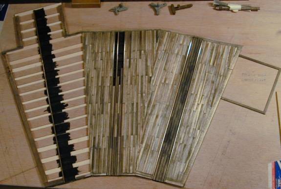
Figure
1, G&D RR Gryme
Roundhouse Floor Plan and Flooring.
The
next photo (Figure 2) shows the completion of the code 70 rails and all the
flooring including the machine shop and the installation of the walls and
framing for the doors. The machine shop
flooring was extended forward about 6 scale feet to provide an entry platform
for the machine shop. The door sections
are shown laid out on the right on the layout board. I used a 3/4-inch plywood board for a construction base and for
installing the roundhouse on the G&D RR Diorama. Also shown is an HO Scale brass Shay geared locomotive in Bay 2.
Figure
2, G&D RR Gryme
Roundhouse Walls Installed and Door Detail.
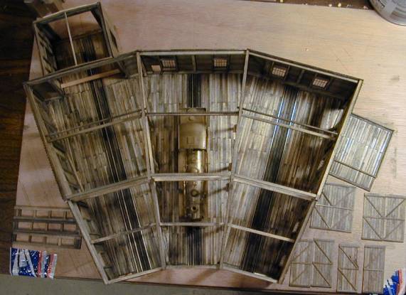
The
Figure 3 photo shows the same construction status as above but from a front
view angle. Here the beams for the
Post-on-Beam roof supports can be seen resting on posts that are better shown
in the next photo which is a side view of the same construction status.
Figure
3, G&D RR Gryme
Roundhouse Post-On-Beam Construction.
In
this next photo (Figure 4) the Post on Beam construction can be seen along with
the installation of the side and rear windows.
The Shay locomotive can be seen in Bay 2.
Figure
4, G&D RR Gryme
Roundhouse Post-On-Beam Construction Detail and Window Installation
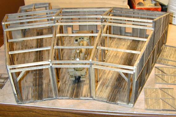
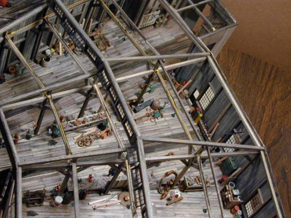
The
Figure 5 photo shows some interior detail that was added by early February 2004
including the compressed air plumbing, electrical lines, fuse boxes and outlets
for each bay.
Figure
5, G&D RR Gryme
Roundhouse Interior Electrical & Compressed Air Plumbing Installation.
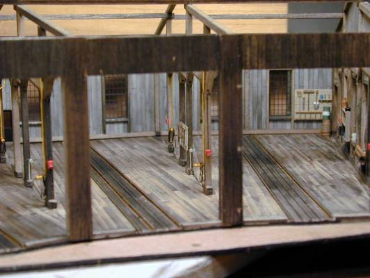
The
next photo (figure 6) shows a better view of the skylight window details and
some interior details that have been installed. The skylight windows are all glazed, as are all the other
windows. These details show up better
in this view. The compressed air
plumbing, electrical lines, fuse boxes and outlets for each bay can also be
seen in this view.
Figure
6, G&D RR Gryme
Roundhouse Interior Detail and Skylight Installation.
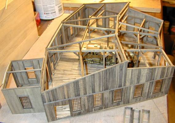
The next step was to
construct the roof sections. By mid
February 2004 I had finished the roof sections and installation. The following photo (figure 7) shows the
roof installation. All of the roof
sections are removable so I can work on the interior details. The roofing is scale corrugated metal and in
this view the machine shop walls have also been installed along with the
roof. Also finished are the door and
window installations for the machine shop, and the skylight windows on the
roundhouse which can be seen here. The
skylight windows that are opened show up fine but the ones that are closed do
not show up well in this view. They
show better in the photo following this one.
The main roundhouse doors (on the layout board on the left) have yet to
be installed because I wanted working door hinges in true scale size and the
various ones I tried to make didn’t work out well in scale size. Also shown are the smoke Vent stacks that
had to be made from scratch.
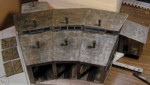
Figure
7, G&D RR
Roundhouse Roof Installation and Smoke Vent Stacks
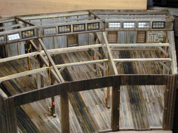
The
next Figure 8 photo shows the progress of interior detailing as of about mid
March. Also shown are the installed
main roundhouse doors that I finally was able to make hinges for.
Figure
8, G&D Gryme
Roundhouse Interior Details and Main Door Installation
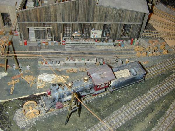
The
Figure 9 photo below shows a portion of some individual details I finished
prior to installation including various work benches (FSM details) and other
scratch- built details.
Figure
9, Some Details
that are (or will be) Installed in the G&D RR Gryme Roundhouse.
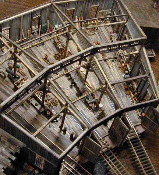
The next photo (Figure 10)
shows some additional progress on the interior details. The true to scale
interior lights (with the green shades) can be seen hanging from the beams over
each bay. The lights are wired and are
functional. The bulbs are the smallest
bulbs available that actually function and work on 1.5 volts. The interior detail is not finished; much
more clutter and dirt and grime needs to be added along with the workers and
engines under repair.
Figure
10, G&D Gryme
Roundhouse Interior Detail Progress.
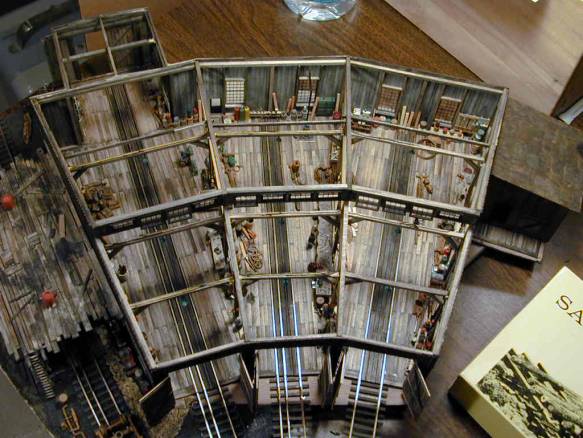
Figure
11 below shows the roof of the added lean-to work shed area adjoining the left
side of the roundhouse for Track/Bay #4.
The shed roof has two water barrels on top in case of fire.
Figure
11, G&D RR
Gryme Roundhouse Interior Detain and Added Lean-To Work Shed area on the left.
The
next photo (Figure 12) shows the temporary fit check of the roundhouse
installation on the G&D RR diorama on or about April 2004. This shows a better overall view of the
roundhouse lean-to work shed area (the water barrels have been removed from the
shed roof in this view).
Figure
12, G&D RR
Gryme Roundhouse Installed on Diorama showing the Lean-To Work Shed Detail.
The
Figure 13 photo shows an overall view of the temporary roundhouse installation
and the “Armstrong” turntable modeled after the prototype one in Laws,
California. The scenery around the
roundhouse is not started in earnest and much more must be done for this scene
to be complete. Additional tracks must
be installed and other work finished before this can be completed.
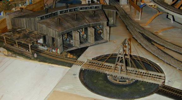
Figure
13, G&D RR
Gryme Roundhouse Installation and Armstrong Turntable
By
about mid April 2004 I installed the tracks leading from the roundhouse to the
turntable and added some scenery details around the roundhouse area. This next photo (Figure 14) shows the status
at that time. The installation of the
additional tracks to the left of the roundhouse for servicing locomotives has
also been started in the lower portion of the photo.
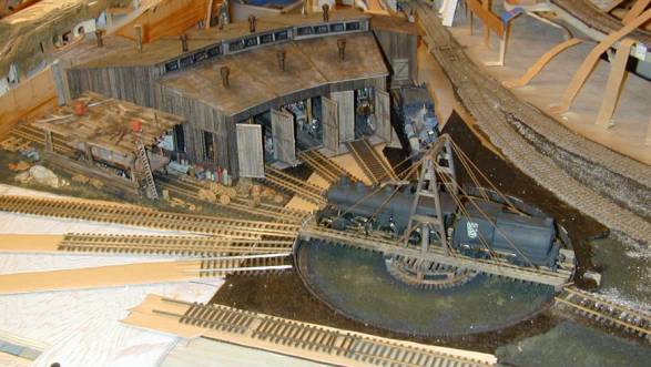
Figure
14, G&D RR
Gryme Roundhouse Installation Progress
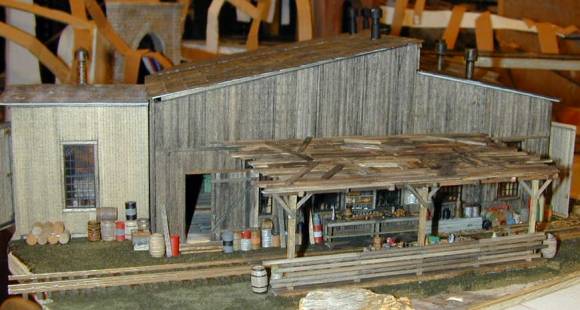
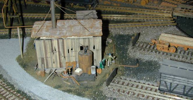
The
next photo (figure 15) is about a year later (Mid 2005), after work has been
done on other areas of the layout. You
can see the auxiliary tracks on the side of the roundhouse have been installed
and the steam power plant for the roundhouse has been installed (bottom
right). The steam supply line from the
power plant to the roundhouse is not completed yet and stops just to the right
of the lean-to work shed. The water
tank for the area has been installed in the upper middle of the photo, just
behind the turntable.
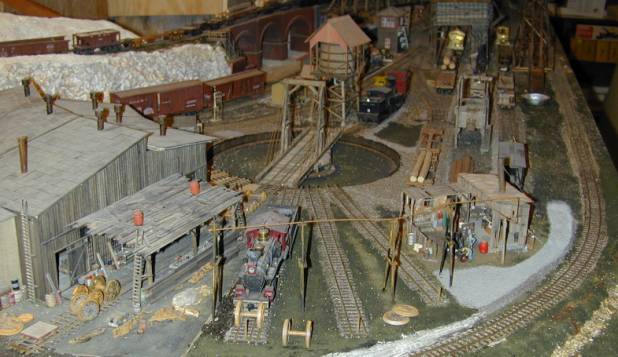
Figure
15, G&D RR
Gryme Roundhouse, Steam Power Plant, and Engine Servicing Area Progress.
The
Figure 16 photo shows the details of the lean-to work shed area with the roof
removed. Also show is the completion of
the steam supply line from the power plant to roundhouse.
Figure
16, G&G RR
Gryme Roundhouse Lean-To Work Shed Detail (roof removed) and Engine Service Area.
This
next photo (figure 17) shows the installation of the A-Frame supports for the
steam supply line. The supply line
comes from the Power Plant at the right in this view and enters the roundhouse
at the rear of the left side (shown better in the previous photo, but without
all the A-Frame supports installed)).
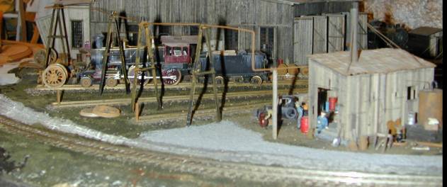
Figure
17, G&D RR
Gryme Roundhouse Steam Power Plant Details and Steam Line Installation.
The next few photos Figures
18 thru 21) show the details of the Power Plant for the Roundhouse. The Power plant started out as a Sierra West
kit with some kit bashing changes and lots of additional details added. The views are from different angles to
better show the details.
For a feel for the actual
size of the structures and the details, a 6-foot man in 1/87 scale (HO scale)
is about 7/8 inches actual size in these photos. As shown below, Figure 20 is slightly larger that actual size,
and Figures 18 and 21 are slightly smaller than actual size. That should give you reference point for the
actual size of some of structures and the details I added. Most of the structures and details are
scratch built (using magnifiers) from various materials that I collected over
time. If kit bashed from a kit I always
mention the name of the kit manufacturer.
If kits are used, they are 95% board-on-board construction.
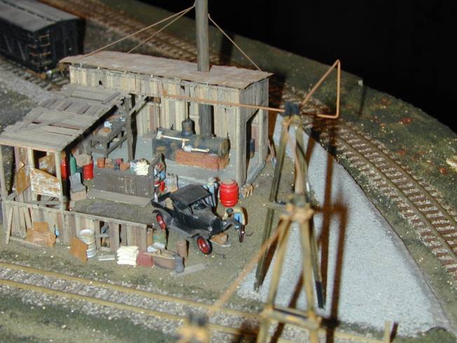
Figure
18, G&D RR
Gryme Roundhouse Steam Power plant Close-Up, North Side.
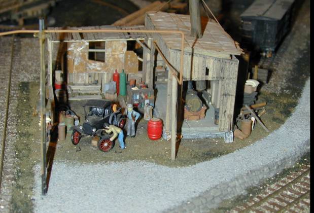
Figure
19, G&D RR
Gryme Roundhouse Steam Power plant Close-Up, West Side
Figure
20, G&D RR
Gryme Roundhouse Steam Power plant Close-Up, South Side
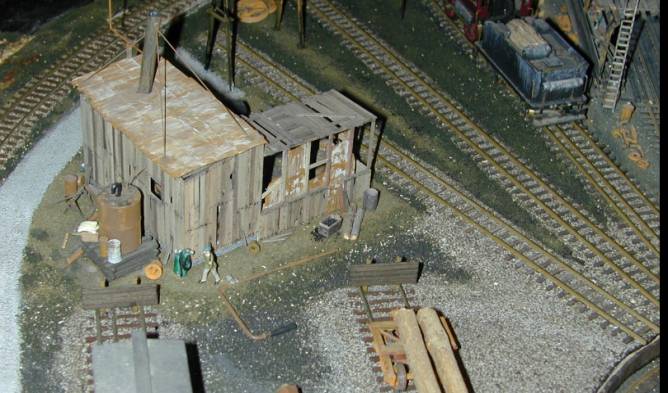
Figure 21, G&D RR Gryme Roundhouse Steam Power plant Close-Up, South & East Sides
CLICK TO RETURN TO FIRST PAGE >> Page 1